Again - not really a new project at all, it just takes me ages to get around to updating this thing.
Awkward silences suck. Whether you're meeting your girlfriend's parents for the first time or making a tasteless joke at a funeral - the threat of a momentary pause in the conversation is an ever-present threat for the not-quite-entirely-antisocial engineer. Unavoidable? Not any more! Introducing Convo, the conversation-starting robot!
The circuit will be relatively simple - one or two minature microphones with amplifiers, a simple microcontroller (I'm using a PIC at the moment, but may switch to the new Value line of MSP430s when my dev kit arrives) with an ADC module, a CompactFlash or MMC card, and a small speaker and amplifier.
The flash card will be loaded with a large number of conversation-sparking sound clips ("How's about them current affairs?!"). The microcontroller will listen out for awkward conversation pauses using the microphones and play a random sound clip when one is detected. It should all be fairly easy to implement, I hope - although it may turn out to be very hard/impossible to get the actual awkward silence detection algorithm working well in all circumstances.
So far I have built the microphone and input amplifier circuit and connected it to a PIC16F819 via a very simple short-term smoothing circuit made from a capacitor and diode. The PIC constantly samples the smoothed output and turns on an LED when it's above a certain level.
Video:
There's only one bug at present - Convo appears to be generating awkward silence. Whenever I explain the idea to someone, my explanation is invariably followed by an extremely awkward silence. I'm not sure why...
Monday, 12 July 2010
Two Good Things

Two Good Things have happened!
1. MSP430 development board for $4.30
Texas Instruments have a new value line of MSP430 processors that seem to be targetting PIC users. They're 16-bit, pretty cheap, and available in DIP packages. Best of all, they're doing "LaunchPad" development boards for a ridiculous $4.30. It includes two of new the MSP430 chips, and they're currently doing free shipping as well. Sadly mspgcc doesn't support them yet, but both TI's Code Composer Studio and IAR's Embedded Workbench have free editions available that are effectively unlimited for the value line chips (they impose a maximum program size, but it's larger than the ROM available on these chips anyway).
The only down-side is that they appear to be on quite a long back order. I ordered mine a couple of weeks ago and was told that they were currently out of stock. No news since, so I think I'll be waiting quite a long time. For about £3, I'm not complaining.
2. A new free PCB design tool
RS Components have released a free PCB design tool called DesignSpark. I've had real problems finding good free PCB design tools, but from the brief play around I've had this one looks excellent for hobbyist use. The user interface in particular seems simple and clean, especially compared to some of the other tools I've tried (Target 3000! comes to mind...) Definitely worth a look.
Train controlling points
As usual, I got this working ages ago and have only just gotten around to writing about it here. I've figured out how to transmit using the CC2420 on the tMote and can now send messages from the train to the points! The train is now running autonomously on a little schedule I've hard coded. It moves to one end of the tracks, sets the points, moves the end of the branch and then back, sets the points to the other branch and moves there, before returning to the start and repeating. Not the most exciting thing in the world, but a big step forward because the train is now autonomously moving about and controlling the points wirelessly itself.
Here's the obligatory dull video!
Here's the obligatory dull video!
Tuesday, 1 June 2010
A train moves!
I've got train with my new circuit design working on the tracks! Hooray! Although I've had this working before, the new design differs in two ways:


The train firmware is very simple at the moment. It accepts messages on the radio from my PC that allow me to start/stop and set the speed. Each time it reaches a reed-switch (positioned at every end of my test track) it automatically stops and reverses direction. Here's an ever so slightly more exciting video!
- The previous design had all the electronics in a carriage towed behind the main engine. While this was asthetically nicer and would allow me to put a nice looking cover on the engine and keep all the electronics hidden, it was somewhat impractical. This was mainly because there were quite a few wires that needed to go between the electronics carriage and the engine (track power pickup +/-, motor drive +/-, front reed switch input. At this stage of the project I want to keep things as simple as possible, so I've moved everything onto a single engine. It's not pretty, but it's much easier to work with. Plus it looks like a robo-train from THE FUTURE, which I kinda like.
- Previously I used a DPDT relay wired in a crossover configuration to reverse the connections to the motor when the train was moving backwards. While I generally like to try and find an excuse to use a relay whenever I can (love that relay *click*), this was a bit of a silly solution - not least because it meant the train used considerably more current when reversing because of the relay coil. I'm now using a 2675 H-Bridge chip borrowed from my housemate for motor direction control. It's a nice little chip to use - although sadly it needs a 5v supply which means I've got two linear regulators on the board (the other is 3v). At some point I'll find a 3v H-bridge. Speed control is using PWM from the microcontroller.


The train firmware is very simple at the moment. It accepts messages on the radio from my PC that allow me to start/stop and set the speed. Each time it reaches a reed-switch (positioned at every end of my test track) it automatically stops and reverses direction. Here's an ever so slightly more exciting video!
Saturday, 29 May 2010
Prototype Points Control Board
Last night I finished a stripboard prototype of my points control board. This connects to the track/points and provides the following to a (seperate) microcontroller board:
 A: Points Control Board
B: Control Mote (using this to test for now, as there is only one set of points. Eventually this'll just a be a PIC/RS485 connection).
C: Microswitch. The points have a useful lever that protrudes out of the side and presses this switch when they're set to the straight ahead position.
D: Points movement solenoid. This is a standard Hornby points motor.
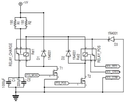
The circuit is very simple. It consists of two large capacitors in parallel (1470μF total) and two MOSFET controlled SPDT relays. The first relay switches the capacitors between charging from the +12v rail and the input of the second relay. The second relay switches between the two terminals of the point movement solenoid.
When the two inputs from the microcontroller are zero, the capacitors charge up. To set the points, the second relay is set to connect to the required side of the point movement solenoid first, and then the first relay is switched so that the current stored in the capacitors flows through the solenoid, moving the points. Because the capacitor discharges quite quickly through the solenoid, there is no danger of doing damage if it is left in the on state.
Here's a rough circuit diagram! (n.b: the two throws of RELAY_CHARGE are the wrong way around in this diagram. I've also left off the linear regulator and microswitch wiring.)
 The firmware running on the control mote is very simple at the moment - it listens on the radio for points control commands and sets the points accordingly. It toggles its red LED every time a message is received and turns on its green LED when the microswitch is open.
I wrote a simple application in C# that uses a Mote connected to a USB port as a way of sending messages over the radio to the control Mote. The video below shows this in action*.
Next on the agenda:
- +3.3v power source. This is taken from the 12v power source on the tracks and converted down using a linear regulator. The regulator can be changed if the microcontroller board requires a different voltage.
- Inputs connected to MOSFETs that allow the points to be switched.
- A logic output that indicates the current position of the points, by way of a microswitch mounted next to them.
 A: Points Control Board
B: Control Mote (using this to test for now, as there is only one set of points. Eventually this'll just a be a PIC/RS485 connection).
C: Microswitch. The points have a useful lever that protrudes out of the side and presses this switch when they're set to the straight ahead position.
D: Points movement solenoid. This is a standard Hornby points motor.
The circuit is very simple. It consists of two large capacitors in parallel (1470μF total) and two MOSFET controlled SPDT relays. The first relay switches the capacitors between charging from the +12v rail and the input of the second relay. The second relay switches between the two terminals of the point movement solenoid.
When the two inputs from the microcontroller are zero, the capacitors charge up. To set the points, the second relay is set to connect to the required side of the point movement solenoid first, and then the first relay is switched so that the current stored in the capacitors flows through the solenoid, moving the points. Because the capacitor discharges quite quickly through the solenoid, there is no danger of doing damage if it is left in the on state.
Here's a rough circuit diagram! (n.b: the two throws of RELAY_CHARGE are the wrong way around in this diagram. I've also left off the linear regulator and microswitch wiring.)
 The firmware running on the control mote is very simple at the moment - it listens on the radio for points control commands and sets the points accordingly. It toggles its red LED every time a message is received and turns on its green LED when the microswitch is open.
I wrote a simple application in C# that uses a Mote connected to a USB port as a way of sending messages over the radio to the control Mote. The video below shows this in action*.
Next on the agenda:
- Building circuitry onto a train that allows it to be controlled from the PC and sense its position.
- Updating the points control firmware so that the current state of the points can be queried over the radio.
- Making the train send points control messages on the radio so that it can set the points as required.
New Project: Model Trains
Ok, this isn't actually a new project as I've been working on it for months now. The aim is to create a model railway that operates in a decentralised automonous way. Here is the basics of how I want it to work:
Now for a really boring video that showed my progress some months ago. It shows a Mote controling a train and simply moving it backwards and forwards by a fixed amount. Nothing very special at this stage...
- Each train will be controlled by an on-board Mote. These are basically small circuits with a microcontroller and radio chip. Trains can communicate with each other wirelessly and form a peer-to-peer mesh network. I am using the (now discontinued) Moteiv tMote Sky model of Mote, as I have five available to me. They have a TI MSP430 MCU and CC2420 2.4GHz radio chip.
- Fixed track features such as points, signals and level crossings will each have a small PIC-based controller. These will all be connected together using a wired RS-485 bus. A single Mote will also be connected to this bus and will act as a wireless interface to all of the fixed features.
- Trains will have knowledge of the track layout, which will be divided up into blocks. The boundary between blocks will have some form of marker embedded under the track so that trains know when they have entered a block. Trains will use dead-reckoning within blocks to estimate their position.
- Each train will allow its schedule to be programmed into it. This will consist of a list of waypoints (stations) that it should visit. Trains will use their knowledge of the track layout to plan a route and follow their schedule.
- Trains will communicate wirelessly to ensure that no block of track is occupied by more than one train at once. This will be done with a token passing protocol, where trains may hold the token for a number of track segments and pass them to other trains as required.
- The fixed track features (e.g. points) will be controlled by the trains themselves by sending messages on the radio to the Mote that is acting as an interface to the fixed features. For example, if a train holds the control token for a block of track with a set of points in, it will be able to set the points as required by its route.
Now for a really boring video that showed my progress some months ago. It shows a Mote controling a train and simply moving it backwards and forwards by a fixed amount. Nothing very special at this stage...
Hello!
This is a blog for me to post updates about things I'm working on. Will I ever update it again? Who knows. Will anyone read it? Almost certainly not.
Good times.
Good times.
Subscribe to:
Posts (Atom)