- +3.3v power source. This is taken from the 12v power source on the tracks and converted down using a linear regulator. The regulator can be changed if the microcontroller board requires a different voltage.
- Inputs connected to MOSFETs that allow the points to be switched.
- A logic output that indicates the current position of the points, by way of a microswitch mounted next to them.
 A: Points Control Board
B: Control Mote (using this to test for now, as there is only one set of points. Eventually this'll just a be a PIC/RS485 connection).
C: Microswitch. The points have a useful lever that protrudes out of the side and presses this switch when they're set to the straight ahead position.
D: Points movement solenoid. This is a standard Hornby points motor.
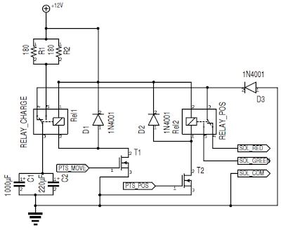
The circuit is very simple. It consists of two large capacitors in parallel (1470μF total) and two MOSFET controlled SPDT relays. The first relay switches the capacitors between charging from the +12v rail and the input of the second relay. The second relay switches between the two terminals of the point movement solenoid.
When the two inputs from the microcontroller are zero, the capacitors charge up. To set the points, the second relay is set to connect to the required side of the point movement solenoid first, and then the first relay is switched so that the current stored in the capacitors flows through the solenoid, moving the points. Because the capacitor discharges quite quickly through the solenoid, there is no danger of doing damage if it is left in the on state.
Here's a rough circuit diagram! (n.b: the two throws of RELAY_CHARGE are the wrong way around in this diagram. I've also left off the linear regulator and microswitch wiring.)
 The firmware running on the control mote is very simple at the moment - it listens on the radio for points control commands and sets the points accordingly. It toggles its red LED every time a message is received and turns on its green LED when the microswitch is open.
I wrote a simple application in C# that uses a Mote connected to a USB port as a way of sending messages over the radio to the control Mote. The video below shows this in action*.
Next on the agenda:
- Building circuitry onto a train that allows it to be controlled from the PC and sense its position.
- Updating the points control firmware so that the current state of the points can be queried over the radio.
- Making the train send points control messages on the radio so that it can set the points as required.